Controller V1.0 finished
The idea of the controller changed once more, but this time it works and I'm satisfied with it.
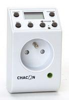
Instead of looking for a system to start it and another one to stop it there are cheap systems available that do all that and much more without any difficulties. I used the timer you can see on the picture, it is designed to work on 240V but since it is digital it must use a lower voltage internally. Another positive side is that it only costs 8.30€.
Inside the whole system consists of 3 parts: the power plugs, the digital part and the small circuit board that changes 240V AC to 24V DC and 3V DC and switches the relay.
The 24V is used to drive the relay so we won't be using that, the 3V is used to power up the digital part and that is what we need.
Since the current consumption of the motor is very low I can switch it using a transistor only. I will post the design of the controller board soon together with pictures of the prototype.
The internals are completely stripped out and only the digital part remains. 3 wires are coming out of that PCB: power and 1 control line. The 3V will be made using an LM317 (adjustable voltage regulator) and the switching will be done with a BC547C (NPN transistor)
WARNING: INSIDE THIS SYSTEM ARE MANY PARTS CONNECTED THE THE MAINS. DO NOT TOUCH ANYTHING WHILE THE SYSTEM IS CONNECTED TO THE POWER. IN FACT, DO NOT OPEN IT AT ALL UNLESS YOU ARE 100% SURE OF WHAT YOU ARE DOING. I AM IN NO WAY RESPONSIBLE TO WHAT YOU DO TO YOURSELF, RELATIVES OR THE TIMER
posted by Miyagi @ 11:38 p.m.
![]()
![]()

0 Comments:
Een reactie posten
<< Home