new power supply
Unfortunately I couldn't get the switching regulatiors from my last post :-(
But there are still other companies that make those things!!!
I got a regulator from TI but the effeiciently only became good at 1A and more so it was not usefull
Now I'm waiting for a
MAX5033 that would do the job. I'll keep you posted as soon I receive the part.
Power consumption problem
With the controller finished, I could start calculating the power needed to keep this system running forever.
The current flowing into the controller is 20mA which means I would consume 0.5 Ah per day. The two solar panels I will use to provide the power give 100mA together in full sun, but only 25mA when it is cloudy.
So I have a problem, a big problem: the battery will slowly drain at a rate of 0.2 Ah per day when there is no full sun (which we never have in Belgium)
The only thing I have actual control over is the DC-DC conversion from 12V to 3V. Using an LM317 like in the current design has a efficiency of about 26%. These chips always have the same ingoing current as outgoing current and will convert the difference to heat.
A small calculation:Consumption: 20mAInput voltage: 12VOutput voltage: 3.15V
Output power = 3.15V * 20mA = 63mW
Input power = 12V * 20mA = 240mW
Efficiency = 63mW / 240mW = 26%
Lost energy = 240mW - 63mW = 177mW
So this current system is very good to keep the PCB at a nice temperature but not to be powered by a solar panel.
Solution
Browsing through the site of
national semiconductor I found their WebBench that could calculate for me the best component to use. They suggested two devices:
-
LM2931: A linear regulator with an efficiency of 27.5% (This is actually the same as my LM317 but fixed set to 3.3V instead of adjustable)
-
LM2676-3.3: A switching regulator with an efficiency of 86%
Using the second one would make my design slightly more complicated but would solve all my problems.
When the consumption of the controller is 63mW and the regulator has an efficiency of 86% the consumption at the input will be: 63mW / 86% = 73mW
73mW at 12V means a current of 6.10mA
luckily they have a TO-220 package: the LM2676T-3.3. It has a maximum current of 3A which is much more then I need but it is the only one that is not SMD.
I expect to have my components in about two weeks so I can finaly finish the board and install the system.
Diagram of the controller
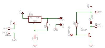
This is the controller. The left part is an LM317 with two resistors calculated to give 3.15V which was exactly what was supplied from the PCB I removed from the timer. The formula for the setting is: Vout = 1.25 * ( 1 + R2/R3) = 1.25 * ( 1 + 330 / 220 ) = 3,125V
It took me about 2 hours and a lot of tests to find out that the output of the timer is not simply giving 0.7V like I measured but actually sinking to ground when the status is set to off.
The resistor in the base of the transistor is calculated to create 240µA in the base so the amplified current will be more then 100mA which is the maximum a BC547C can drive. The motor will only consume about 30mA so that is more then enough. I have included a diode to absorb the reflow then motor may cause when the power is removed.
Controller V1.0 finished
The idea of the controller changed once more, but this time it works and I'm satisfied with it.
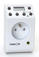
Instead of looking for a system to start it and another one to stop it there are cheap systems available that do all that and much more without any difficulties. I used the timer you can see on the picture, it is designed to work on 240V but since it is digital it must use a lower voltage internally. Another positive side is that it only costs 8.30€.
Inside the whole system consists of 3 parts: the power plugs, the digital part and the small circuit board that changes 240V AC to 24V DC and 3V DC and switches the relay.
The 24V is used to drive the relay so we won't be using that, the 3V is used to power up the digital part and that is what we need.
Since the current consumption of the motor is very low I can switch it using a transistor only. I will post the design of the controller board soon together with pictures of the prototype.
The internals are completely stripped out and only the digital part remains. 3 wires are coming out of that PCB: power and 1 control line. The 3V will be made using an LM317 (adjustable voltage regulator) and the switching will be done with a BC547C (NPN transistor)
WARNING: INSIDE THIS SYSTEM ARE MANY PARTS CONNECTED THE THE MAINS. DO NOT TOUCH ANYTHING WHILE THE SYSTEM IS CONNECTED TO THE POWER. IN FACT, DO NOT OPEN IT AT ALL UNLESS YOU ARE 100% SURE OF WHAT YOU ARE DOING. I AM IN NO WAY RESPONSIBLE TO WHAT YOU DO TO YOURSELF, RELATIVES OR THE TIMER
Contoller V0.1
The plans for the first type of controller are made. Since special hardware might become very expensive the idea is to hack into existing sytems.
Instead of using a real time clock and processor I might as well use a digital clock and get my signal from the buzzer. That way I can easely program the system to start dispensing the food at a certain time.
The second problem is that the transport system has to run for a couple of minutes and then turn off. In my enthousiasm I bought a digital kitchen timer that can be configured up to 99 minutes and 59 seconds.
The diagram using a flip-flop was already made on paper when I realised that any small fault in the system would cause the transporter to stop working or even keep on working forever.
In case the battery of the kitchen timer went flat the sytem would start but would never got a signal to turn it off again.
That is why a version V0.2 is already in progress. It will still use a digital clock as initial trigger but more robust timer will control the motor. My first idea was to use
this velleman kit but the specs show it consumes 20mA. Unless I find something to reduce that, it might become too much for my solar panels with a maximum production of 100mA (in full sunlight)
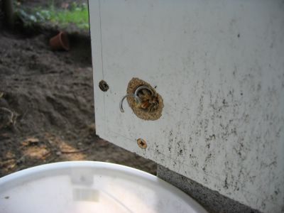
The transporter in action. Some protection will be added in the future and a tube to get the food in the bowl.
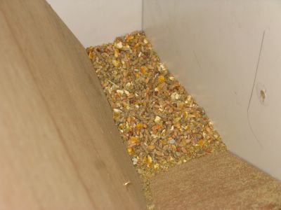
The silo filled with food
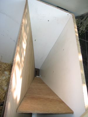
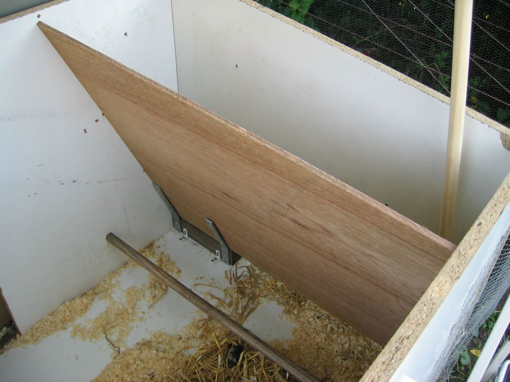
Triangle inside the silo to guide the food to the transporter. It also creates a clean area where the motor is and the controller will be

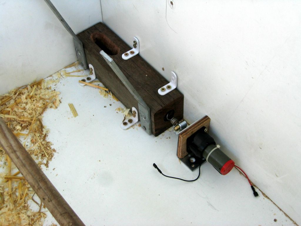
The motor in place
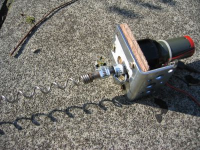
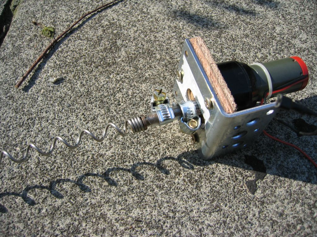
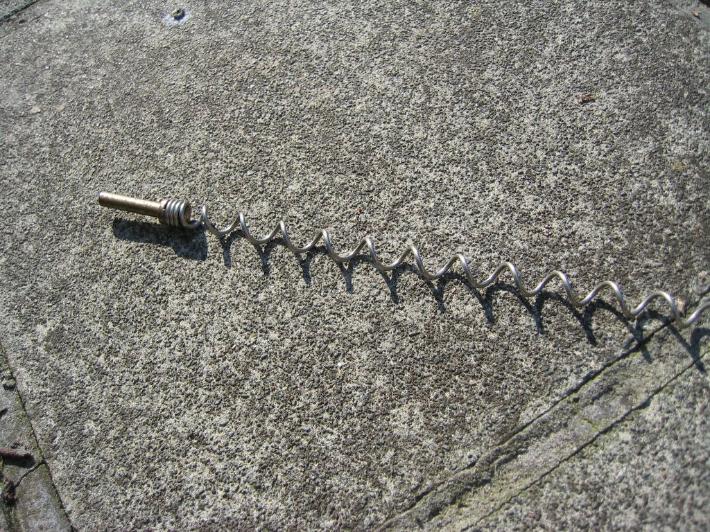
The motor with the spiral attached
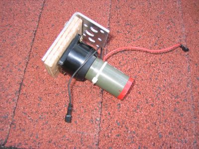
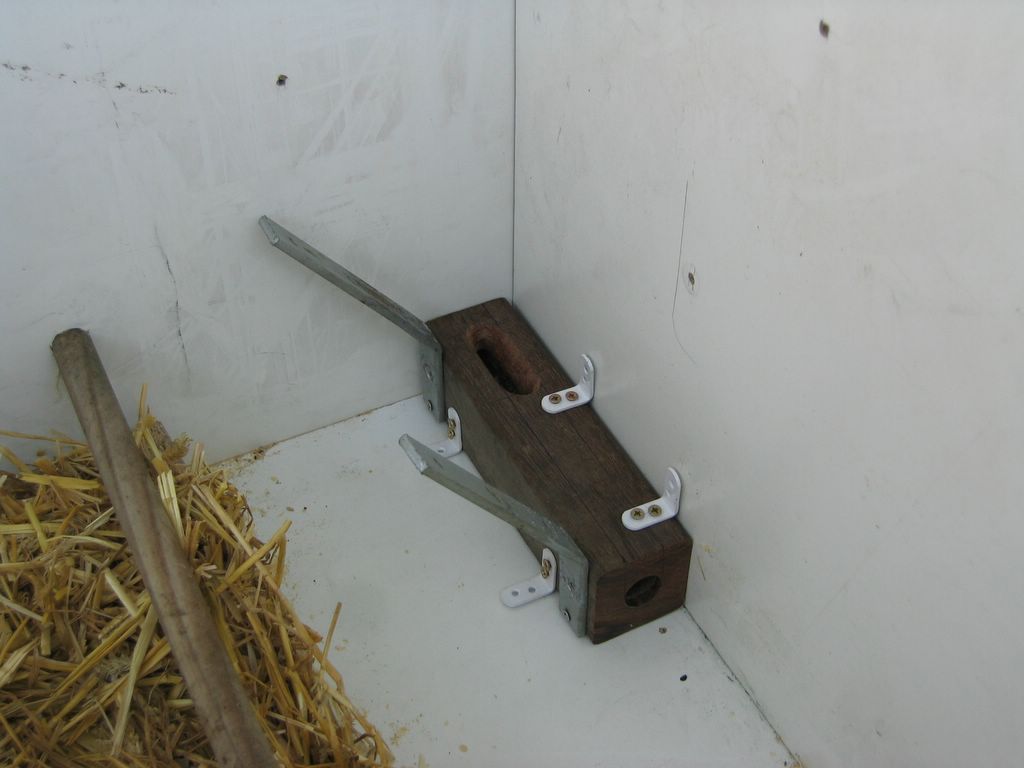
The motor installed on the mountnig plate
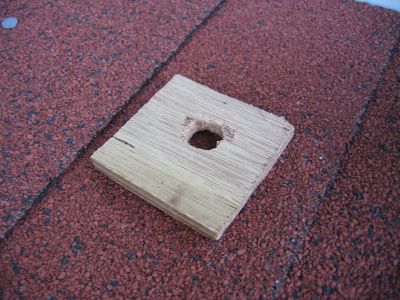
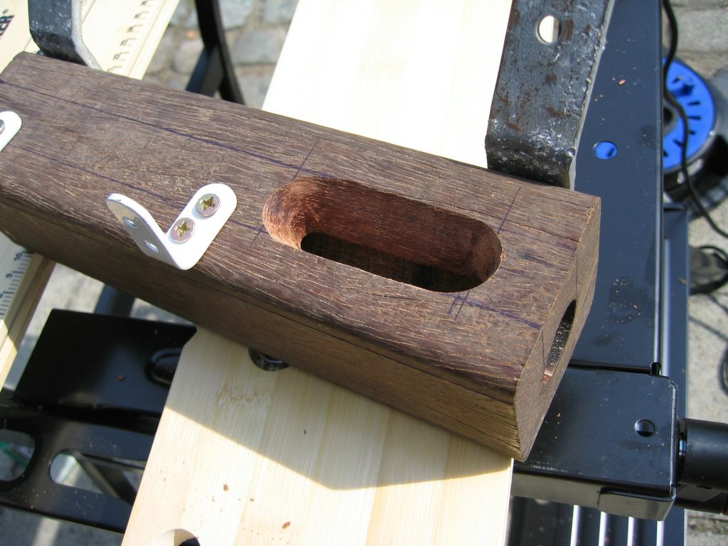
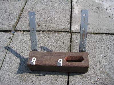
A small piece of wood to buffer and mount the motor

This little fellow will hold the motor. The slot in the middle is big enough for the shaft but not for the piece holding the shaft
view from the top inside the silo

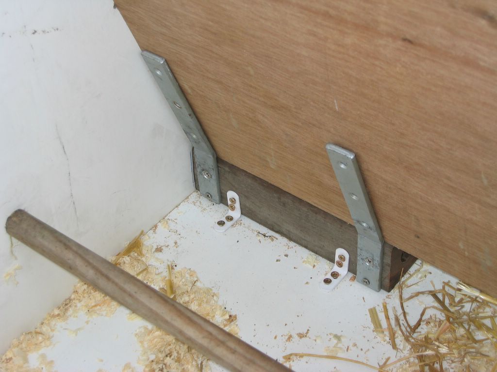
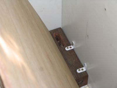
Connection of the plate to the transporter

The wooden plate of the silo in place
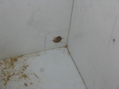
The hole in the side wall to pass through the food
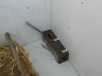
The transporter in place
A wider view of the transport system

A closeup of the transport system. The grains will fall in the slot and will be transported out of the hole at the right
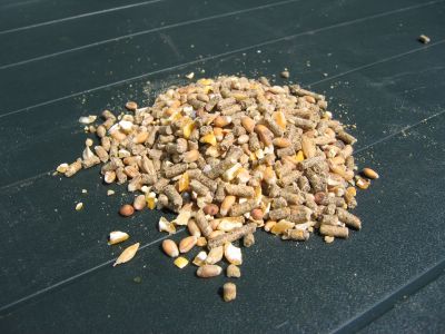
The food :-)
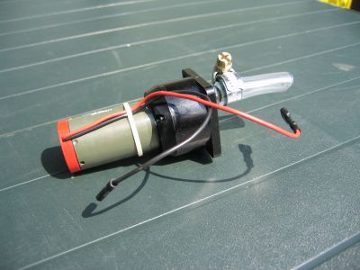
small motor with a piece of tube attachted to it, the tube will make the connection between the shaft of the motor and the spiral

This spiral will do the transport of the food. I have decided to use this instead of the drill because this can never get stuck and requires less torque to rotate. The flow is slightly lower but since the power consumption of the small motor much lower is then for the bigger one, I will save power.
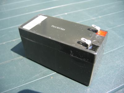
Lead acid battery, this has a capacity of 1Ah and should last a few months. In the near future, solar panels will be added to keep the sytem powered

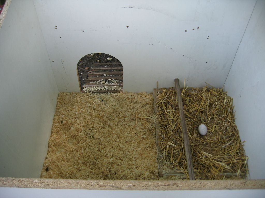
Inside the house before any changes were made
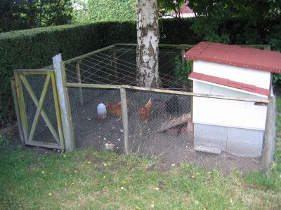
Their complete world, the extra shelter in the front was added to keep their food dry
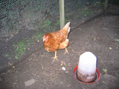
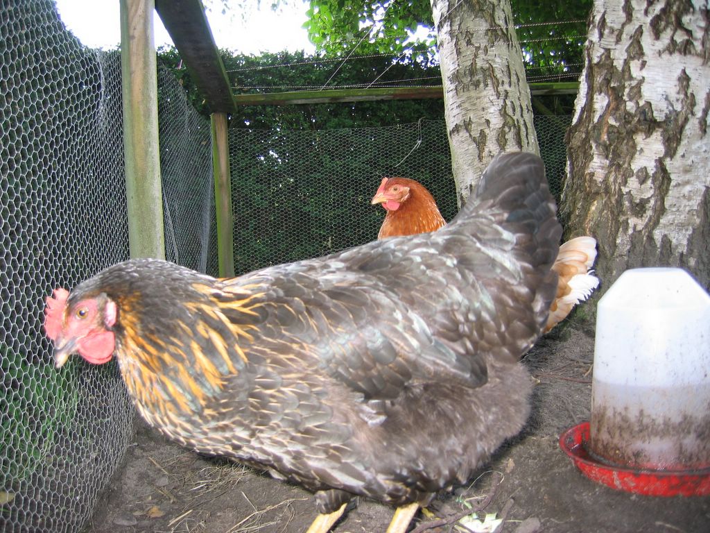
Anne in action
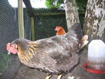
Denise in the front and Anne at the back
construction and installation
A sunny sunday is all it takes to go shop for the needed tools and install the system.
Just before installation I have decided to change the transport system to version V1.0. It no longer uses the drill as the actual worm. The whole thing worked fine until a piece of stone (chickens eat that to grind the food in their stomach) got cought between the drill and the wooden block. Since stone, steel and hardwood all are pretty tough, it was the motor who had to make the sacrifice. Result, the system jammed and I had to turn it backwards to remove the stone. In real life this would mean that my chickens would starve.
The solution to this was a simple spiral turning freely in the much bigger pipe. The spiral has a diameter of 10mm the pipe is 22mm. If I knew this before the start of the project it would have saved me an expensive drill, but hey, that's always nice to have.
- Drill a hole of the same size in the sidewall of the house exactly where the transport tunnel will come
- The transport block is installed in the corner of the house using L-shaped mounting plates. It is needed to drill a hole in the hardwood first where the screws will come because getting a standard screw in is impossible.
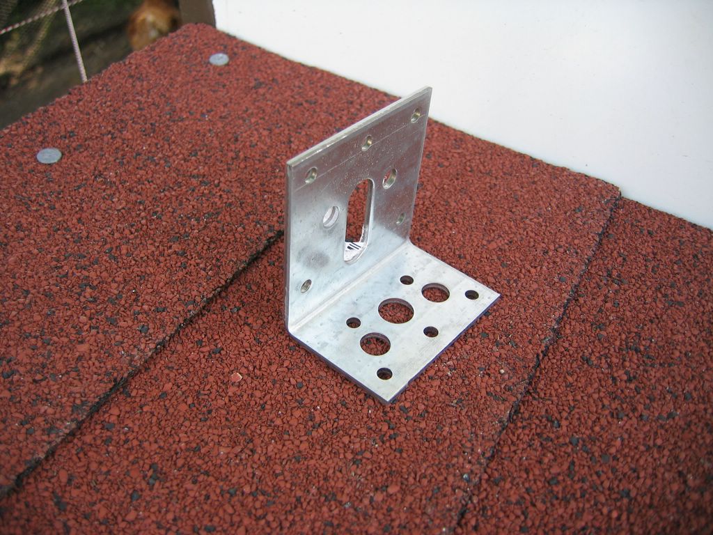
- The motor will be mounted against a large L-shape mounting plate that already had a slot of 10mm width where the shaft fits in. I had to add a small piece of wood because the part where the shaft came out was slight bigger then 10mm.
- A small piece of tube and two clamps will firmly connect the spiral to the shaft of the motor.
- The spiral is passed throught the tunnel and the motor is mounted so there is enough space to let the clamps turn freely. Because we used platic tube to connect them, it can buffer any variations in the movement.
- At the sides of the transport block there is are two L-shaped mounting plates that were bend to a much bigger angle of about 165°. These will hold the sideplate to create the food silo.
- Inside the silo a triangle is installed to bring all the food to the transporter (my photo's will explain that much better)
That's about all what is done now. So the harware contruction is completed, tested and working fine. Next step is the controller that will turn the system on in the morning to provide the food. The design of that is only in the first stage but you will find more progress here soon
First prototype made + actual model
The first test was very succesfull, the drill was able to transport the food and didn't get stuck at any point.
Making the actual model was a different story though. Since I was affraid of the wooden block wearing out by the drill I used a piece of tropic hardwood. (thanks dad for supplying that).
On small remark though: tropic hardwood is HARD!!!
It costed us 30 minutes to drill about 10cm deep. With smoke coming out of the wooden block and the power drill, something had to go wrong. So 5cm before we got through the block my power drill passed away. Thanks to my dads professional power drill we were able to finish the job so I guess this is where you see the difference between a 250 Euro powerdrill and a 29 Euro one :-)
Result: Transport system is almost ready and pictures will be uploaded this weekend (I have my camera back)
Got some hardware
I bought the wood-drill, some plastic tube to connect the drill to the motor
and some clamps. All together is costed me around 20 Euro (the drill was
very expensive). Hopefully this evening I can create the first prototype to
have a proof of concept
Transport system V0.2
I told you it would change in the future :-)
I just realised that there is a small problem with version 0.1. Since it has
an L-shaped tunnel, the food will come out at the bottom.
The idea was to drill a hole in the bottom plate of the chickenhouse but as
you can see in the picture there are concrete blocks just below the edges.
V0.2 will go straight to the sidewall and drop the food at the side. I will
need to add some protection to avoid injury and prevent water from flowing
in the transport system.
Front view diagram

This simple diagram gives an idea of how the installation will be done. More details on the transporter will follow.
Materials and tools needed
Materials - Wooden plate
- Piece of wood (about 5cm*5cm*25cm)
- Slowly rotating motor. I used a 12V motor with a reduction system from an old copier. It is imporant that it has a low speed (about 100 RPM) and a high torque
- lots of screws
- Large wood-drill, it's important that it has a deep cut to transport the food
- small piece of tube, to connect the drill to the motor (both the shaft of the motor and the drill have to fit in the tube)
- clamps to fasten the tube around the shaft and drill
Tools - Drill
- Saw
- Screwdriver
- Sandpaper
The transport system V0.1
I have labeled this V0.1 because I can imagine it changing a couple of times in the future.
Since the weight of the grain and the size of the individual grains, a valve doesn't seem possible in my opinion. There would always be something stuck in between causing it not to open or close properly.
What should work is a wormwheel (don't know if that is the right term) but since I have absolutely no idea where to find that I'll have to make one myself using a large wood-drill. The idea is to drill an L-shape tube in a wooden block and let the drill rotate in reverse inside the tube so it transports the grain to the end of the tube where it will fall in the hole into the recepient.
Start of the project
The idea of this project originally came from Tim (thanks mate for finding me a new project).
Allthough I have to visit my chickens every day (to get the eggs) I want an automated feeder system. Why? ..... just because it's cool.
I know there are many feeding systems available in the pet shop but I don't want them to have access to the specialised food the whole day. Exposing them to an unlimited supply of grains, corn, ... would stop them from eating my kitchen waste (and that's why we bought them in the first place).
How will it work
The idea is to mount a wooden plate in the chicken house to create a silo. At the bottom of that silo will come a transport system to get the grains to the feeding place. I will post pictures or diagrams later but at this time the design is only in my head.